- 您现在的位置:买卖IC网 > Sheet目录1993 > DS1306EN/T&R (Maxim Integrated Products)IC RTC SERIAL ALARM IND 20-TSSOP
DS1306
6 of 22
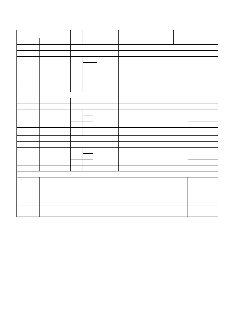
Figure 2. RTC REGISTERS AND ADDRESS MAP
HEX ADDRESS
READ
WRITE
Bit7
Bit6
Bit5
Bit4
Bit3
Bit2
Bit1
Bit0
RANGE
00h
80h
0
10 SEC
SEC
00–59
01h
81h
0
10 MIN
MIN
00–59
P
12
A
01–12 + P/A
02h
82h
0
24
10
10-HR
HOURS
00–23
03h
83h
0
DAY
01–07
04h
84h
0
10-DATE
DATE
1–31
05h
85h
0
10-MONTH
MONTH
01–12
06h
86h
10-YEAR
YEAR
00–99
07h
87h
M
10-SEC ALARM 0
SEC ALARM 0
00–59
08h
88h
M
10-MIN ALARM 0
MIN ALARM 0
00–59
P
12
A
01–12 + P/A
09h
89h
M
24
10
10-HR
HOUR ALARM 0
00–23
0Ah
8Ah
M
0
DAY ALARM 0
01–07
0Bh
8Bh
M
10 SEC ALARM 1
SEC ALARM 1
00–59
0Ch
8Ch
M
10 MIN ALARM 1
MIN ALARM 1
00–59
P
12
A
01–12 + P/A
0Dh
8Dh
M
24
10
10-HR
HOUR ALARM 1
00–23
0Eh
8Eh
M
0
DAY ALARM 1
01–07
—
0Fh
8Fh
CONTROL REGISTER
—
10h
90h
STATUS REGISTER
—
11h
91h
TRICKLE CHARGER REGISTER
—
12h–1Fh
92h–
9Fh
RESERVED
—
20h–7Fh
A0h–
FFh
96-BYTES USER RAM
—
Note: Range for alarm registers does not include mask’m’ bits.
The DS1306 can be run in either 12-hour or 24-hour mode. Bit 6 of the hours register is defined as the
12- or 24-hour mode select bit. When high, the 12-hour mode is selected. In the 12-hour mode, bit 5 is the
AM/PM bit with logic-high being PM. In the 24-hour mode, bit 5 is the second 10-hour bit (20 to 23
hours).
The DS1306 contains two time-of-day alarms. Time-of-day alarm 0 can be set by writing to registers 87h
to 8Ah. Time-of-day Alarm 1 can be set by writing to registers 8Bh to 8Eh. Bit 7 of each of the time-of-
day alarm registers are mask bits (Table 2). When all of the mask bits are logic 0, a time-of-day alarm
only occurs once per week when the values stored in timekeeping registers 00h to 03h match the values
stored in the time-of-day alarm registers. An alarm is generated every day when bit 7 of the day alarm
register is set to a logic 1. An alarm is generated every hour when bit 7 of the day and hour alarm
发布紧急采购,3分钟左右您将得到回复。
相关PDF资料
DS1307N
IC RTC SERIAL 512K IND 8-DIP
DS1308U-3+
IC RTC 56BYTE NVRAM I2C 8UMAX
DS1315EN-5/T&R
IC TIME CHIP PHANTOM 20-TSSOP
DS1318E+
IC COUNTER ELAPSED TIME 24-TSSOP
DS1337S+C01
IC RTC SERIAL 2WIRE LP 8-SOIC
DS1338C-33#T&R
IC RTC 56BYTE NV SRAM 16SOIC
DS1339AU+
IC RTC I2C W/ALARM 8USOP
DS1339C-2#
IC RTC I2C W/ALARM 16-SOIC
相关代理商/技术参数
DS1306EN/T&R/C04
功能描述:实时时钟
RoHS:否 制造商:Microchip Technology 功能:Clock, Calendar. Alarm RTC 总线接口:I2C 日期格式:DW:DM:M:Y 时间格式:HH:MM:SS RTC 存储容量:64 B 电源电压-最大:5.5 V 电源电压-最小:1.8 V 最大工作温度:+ 85 C 最小工作温度: 安装风格:Through Hole 封装 / 箱体:PDIP-8 封装:Tube
DS1306EN/TR
制造商:DALLAS 制造商全称:Dallas Semiconductor 功能描述:Serial Alarm Real-Time Clock
DS1306EN+
功能描述:实时时钟 Serial Alarm RTC 3-Wire RoHS:否 制造商:Microchip Technology 功能:Clock, Calendar. Alarm RTC 总线接口:I2C 日期格式:DW:DM:M:Y 时间格式:HH:MM:SS RTC 存储容量:64 B 电源电压-最大:5.5 V 电源电压-最小:1.8 V 最大工作温度:+ 85 C 最小工作温度: 安装风格:Through Hole 封装 / 箱体:PDIP-8 封装:Tube
DS1306EN+T&R
制造商:Maxim Integrated Products 功能描述:REAL TIME CLOCK SERL 96BYTE 20TSSOP - Tape and Reel 制造商:Maxim Integrated Products 功能描述:REAL TIME CLOCK SERL 96BYTE 20TSSOP - Cut TR (SOS) 制造商:Maxim Integrated Products 功能描述:Maxim Integrated DS1306EN+T&R Real Time Clocks (RTC) 制造商:Maxim Integrated Products 功能描述:IC RTC SERIAL ALARM IND 20-TSSOP
DS1306EN+T&R
功能描述:实时时钟 Serial Alarm RTC 3-Wire RoHS:否 制造商:Microchip Technology 功能:Clock, Calendar. Alarm RTC 总线接口:I2C 日期格式:DW:DM:M:Y 时间格式:HH:MM:SS RTC 存储容量:64 B 电源电压-最大:5.5 V 电源电压-最小:1.8 V 最大工作温度:+ 85 C 最小工作温度: 安装风格:Through Hole 封装 / 箱体:PDIP-8 封装:Tube
DS1306EN+TR
制造商:MAXIM 制造商全称:Maxim Integrated Products 功能描述:Serial Alarm Real-Time Clock
DS1306N
功能描述:实时时钟 Serial Alarm RTC 3-Wire RoHS:否 制造商:Microchip Technology 功能:Clock, Calendar. Alarm RTC 总线接口:I2C 日期格式:DW:DM:M:Y 时间格式:HH:MM:SS RTC 存储容量:64 B 电源电压-最大:5.5 V 电源电压-最小:1.8 V 最大工作温度:+ 85 C 最小工作温度: 安装风格:Through Hole 封装 / 箱体:PDIP-8 封装:Tube
DS1306N+
功能描述:实时时钟 Serial Alarm RTC 3-Wire RoHS:否 制造商:Microchip Technology 功能:Clock, Calendar. Alarm RTC 总线接口:I2C 日期格式:DW:DM:M:Y 时间格式:HH:MM:SS RTC 存储容量:64 B 电源电压-最大:5.5 V 电源电压-最小:1.8 V 最大工作温度:+ 85 C 最小工作温度: 安装风格:Through Hole 封装 / 箱体:PDIP-8 封装:Tube